Product manufactured by

MASTER-F panels are structural wall Insulated Metal Panels composed of steel skins laminated to a minimum of 1.96-inch polyisocyanurate foam core (min 2.3 pcf density).
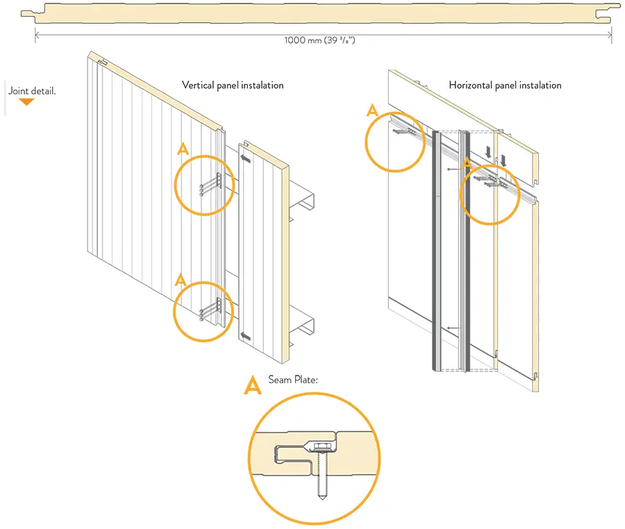
MASTER-F panels have a tongue and groove joining system designed to hide and protect the fixings, which gives an excellent aesthetic appearance. They canbe installed in both vertical and horizontal positions.
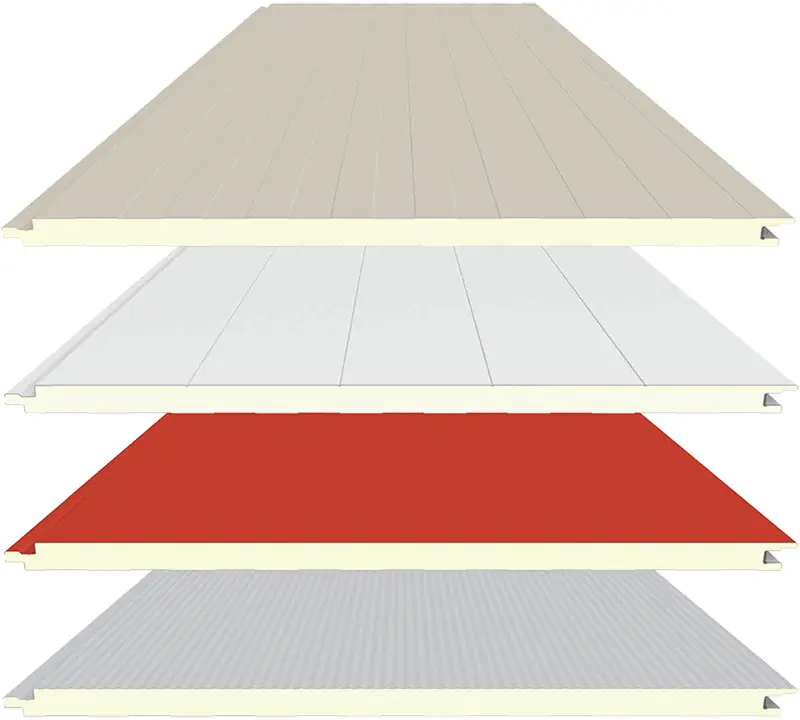
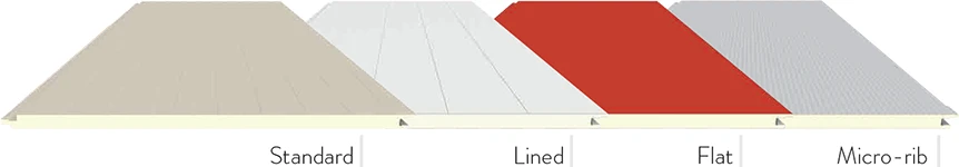
They come in four different exterior finishes (standard, lined, flat, micro-rib) and two different inner ribbings (standard and flat), as well as a wide range of available colors.
TECHNICAL SPECIFICATIONS
| Panel thickness | 50, 60, 80, 100 mm. 1 31/32, 2 3/8, 3 5/32, 3 15/16, inch. |
| Cover Width | 1.000 mm. (39 3/8”) |
| Length | Up to 11.900 mm. (39 ft.) |
| Field of application | Wall panels |
| Outer face thickness: | mm 0.5 / 0.6 / 0.7 |
| Inner face thickness: | GAUGE 26 / 24 / 22 |
| Exterior face: | G90 galvanized or AZ50 aluminium-zinc, coated steel in 26 GA and above |
| Interior face: | G90 galvanized or AZ50 aluminium-zinc, coated steel in 26 GA and above |
| Coatings (see section on Finishes): |
|
| Outer ribbing | Standard / Lined / Flat / Micro-rib |
| Inner ribbing | Standard / Flat |
| Core type | Polyisocyanurate (PIR) |
| Core Density | 40 kg/m³ (+/- 10%) (2.3 PCF) |
| Panel thickness | Panel weight | U-Value | R-Value | |
| mm | inch | PSF | BTU/Hr ft2 0F | Hr ft2 0F/BTU |
| 50 | 1 31/32 | 2.17 | 0.075 | 13.28 |
| 60 | 2 3/8 | 2.25 | 0.062 | 16.17 |
| 80 | 3 5/32 | 2.41 | 0.046 | 21.59 |
| 100 | 3 15/16 | 2.58 | 0.037 | 26.99 |
Calculations according to EN14509, measuring the surface resistance according to horizontal flow and omitting the influence of the profiled faces. Losses in bolted connections must be calculated by the designer.
REACTION TO FIRE
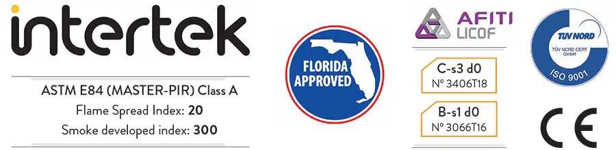
Testing and approvals:
Master Panel wall panel meet the most demanding requirements. We have large experience in producing insulated metal panels in our continuous production line and we have obtained the FL approval with reference #FL27199.
| TEST | TEST METHOD | RESULTS |
| FIRE | ASTM E 84 | Flame spread index 20 Smoke developed index 300 |
| Strength | ASTM E 8 | > 32 ksi steel |
| Wind Uplift | ASTM E 330 | Design load up to 67.5 psf | Water penetration | ASTM E 331 | No water leakage at 12 psf | Permeability | ASTM E 283 | < 0.004 cfm/ft2 at 12 psf |
| Master-F Wall Panel | ||||
| Panel Description | Support Spacing (in) |
Allowable Inward Load (psf) FD1 & FD 2 |
Allowable Inward Load (psf) | |
| FD1 | FD2 | |||
|
Master F Min. 26 ga. Exterior & Interior Skins Panel Core Thickness: 1-31/32”, 2-3/8”, 3-5/32” 3-15/16”, 4-23/32”, 5-15/16” (50, 60, 80, 100, 120 & 150 mm) |
||||
| 36 | 132.5 | 34.5 | 67.5 | |
| 39 | 122.3 | 33.7 | 65.4 | |
| 42 | 113.6 | 32.8 | 63.3 | |
| 48 | 99.4 | 31.2 | 56.3 | |
| 54 | 88.3 | 29.5 | 50.0 | |
| 60 | 79.5 | 27.8 | 45.0 | |
| 66 | 72.3 | 26.2 | 40.9 | |
| 72 | 66.3 | 24.4 | 37.5 | |
| 78 | 61.2 | 22.5 | 34.6 | |
| 84 | 56.8 | 20.9 | 32.1 | |
| 90 | 53.0 | 19.5 | 30.0 | |
Notes:
- Allowable load is the lowest value of panel strength, connection strength & defl ection limit of L/180.
- Allowable load is aplicable to two or more span conditions.
- The bold numbers indicate design loads obtained from test reports.
- Panels must be installed as per Evaluation Report FL27199.1 and Master Panel current installation procedure.
- For Fastening Design FD1, U-clips are fastened to min. 14 ga. steel with (2) 1/4”-14 Type 3 SDS or to min. 16 ga. steel with (3) 1/4’-14 Type 3 SDS at all supports.
- The Fastening Design FD2 includes U-clip attachment plus 3 Fab-loks fasteners per panel width at supports. Fastener spacing is 9.8” (250 mm) o.c. from female edge of panel seam.
- Continuous bead of Dow Corning® 791 silicone weatherproofi ng sealant was fi eld applied along the panel seams.
- The structural capacity of support beam are not considered and must be examined independently by others.
- Minimum bearing width of support is 2.5”.
Colour chart
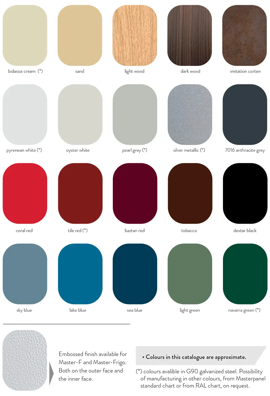
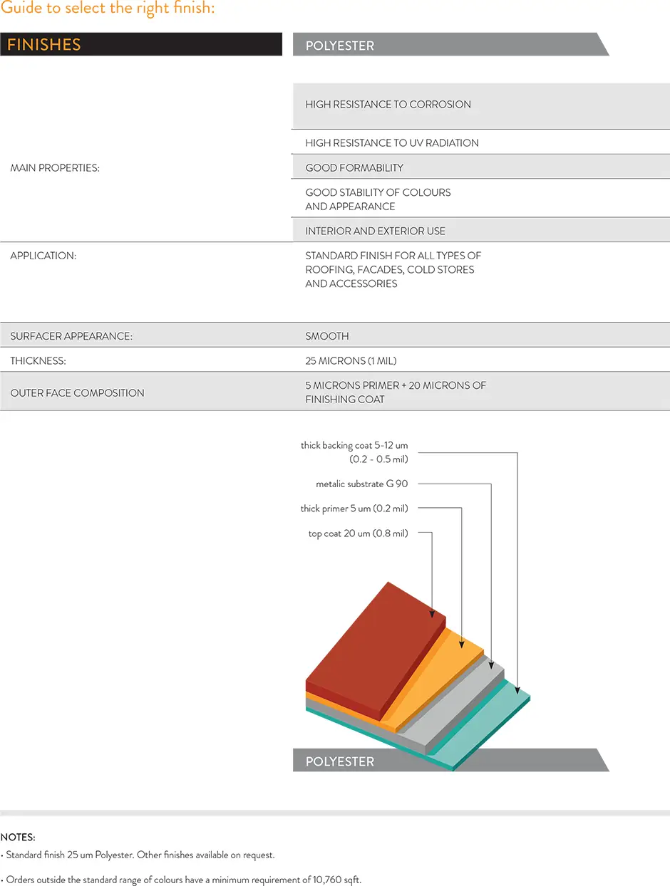
Guide to select the right finish:
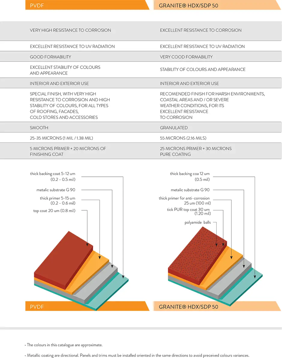
In order to choose the right prepainted finish for each use, the planner responsible for the design of the project must take into account both the incidence of UV rays and the exposure to corrosive environments of the building or project.
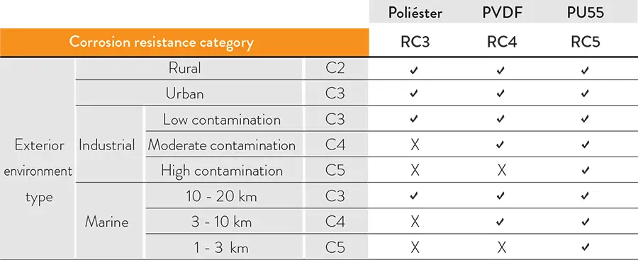
- Corrosion resistance of the paint system
To determine the corrosion resistance of a paint system, it is subjected to the salt spray test. This test evaluates the appearance of corrosion after a number of hours in a saline mist chamber. The results provide each paint scheme with an RC corrosion resistance value, from RC1 to RC5, with RC1 being the lowest value. This means that those RC3 rated paint schemes have shown their suitability for environments rated C3 or lower. - Resistance to UV radiation of the paint system
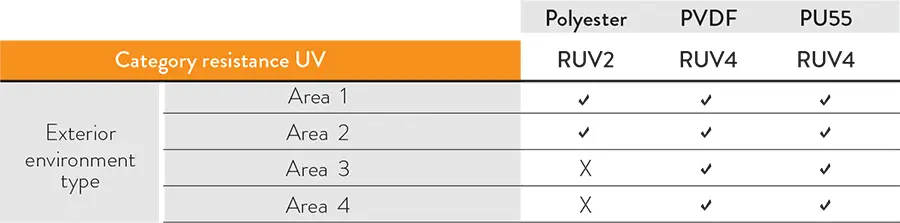
To determine the UV resistance of a paint system, it is subjected to the QUV accelerated aging test. This test evaluates the loss of gloss and colour over time due to UV rays. The results provide each paint scheme with a UV resistance value RUV, from RUV1 to RUV4, with RUV1 being the lowest value. - Classification of environments
| DESCRIPTION OF CORROSIVE CATEGORIES FOR EXTERNAL ENVIRONMENTS | |
| C1 | Very low. |
| C2 | Low: Areas with low level of contamination. Mainly rural or industrial areas without incidence by sulphur dioxide. |
| C3 | Moderate: Urban and industrial areas with low sulphur dioxide (SO2) pollution and coastal areas with low salinity (from 10 km to 20 km from the sea). |
| C4 | High: Industrial areas with moderate contamination by sulphur dioxide (SO2) and coastal areas with moderate salinity (from 3 km to 10 km from the sea). |
| C5 I | Very high: Industrial areas with very aggressive atmospheres and high contamination by sulphur dioxide (SO2) |
| C5 M | Very high: Coastal and maritime areas with high salinity (from 1 km to 3 km from the sea). |
| Corrosive environment category |
Environment type | |||||||||||
| Rural | Urban | Industrial | Marine | |||||||||
| C1 - very low | ||||||||||||
| C2 - low | ||||||||||||
| C3 - moderate | SO2 low | (10-20 km) | ||||||||||
| C4 - high | SO2 moderate | (3-10 km) | ||||||||||
| C5 I - very high | SO2 high | |||||||||||
| C5 M - very high | (1-3 km) | |||||||||||
| DESCRIPTION OF THE CATEGORIES OF UV RESISTANCE FOR EXTERNAL ENVIRONMENTS | |
| Area 1: | Areas with low exposure to UV radiation or without special colour maintenance requirements. |
| Area 2: | Areas with low exposure to UV radiation or without special colour maintenance requirements. |
| Area 3: | Areas with moderate exposure to UV radiation. |
| Area 4: | Areas with high exposure to UV radiation or with special colour maintenance requirements. |
- Choice of finishes for different environments
Once the category of the environment is known, the person responsible for the design must decide on the painting system:
- The suitable paint system needs to be determined in terms of corrosion. The following table can be used as a guide.
- The suitable paint system in terms of UV radiation have to be determined. The following table can be used as a guide.
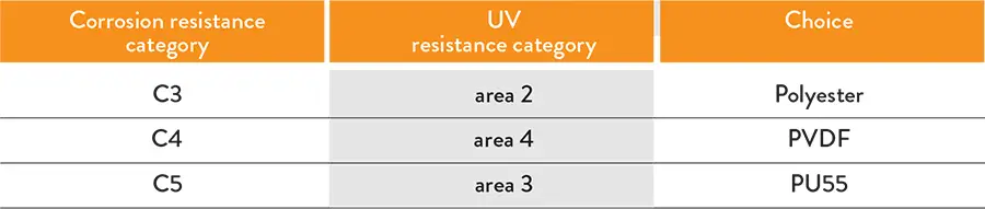
- A suitable paint system should be chosen in terms of both corrosion resistance and UV resistance. The following cases can be used as a guide.
The data stated in the tables is informative and does not constitute a guarantee of the material. You should contact Masterpanel about any applications which require a guarantee for the steel in the panels.